
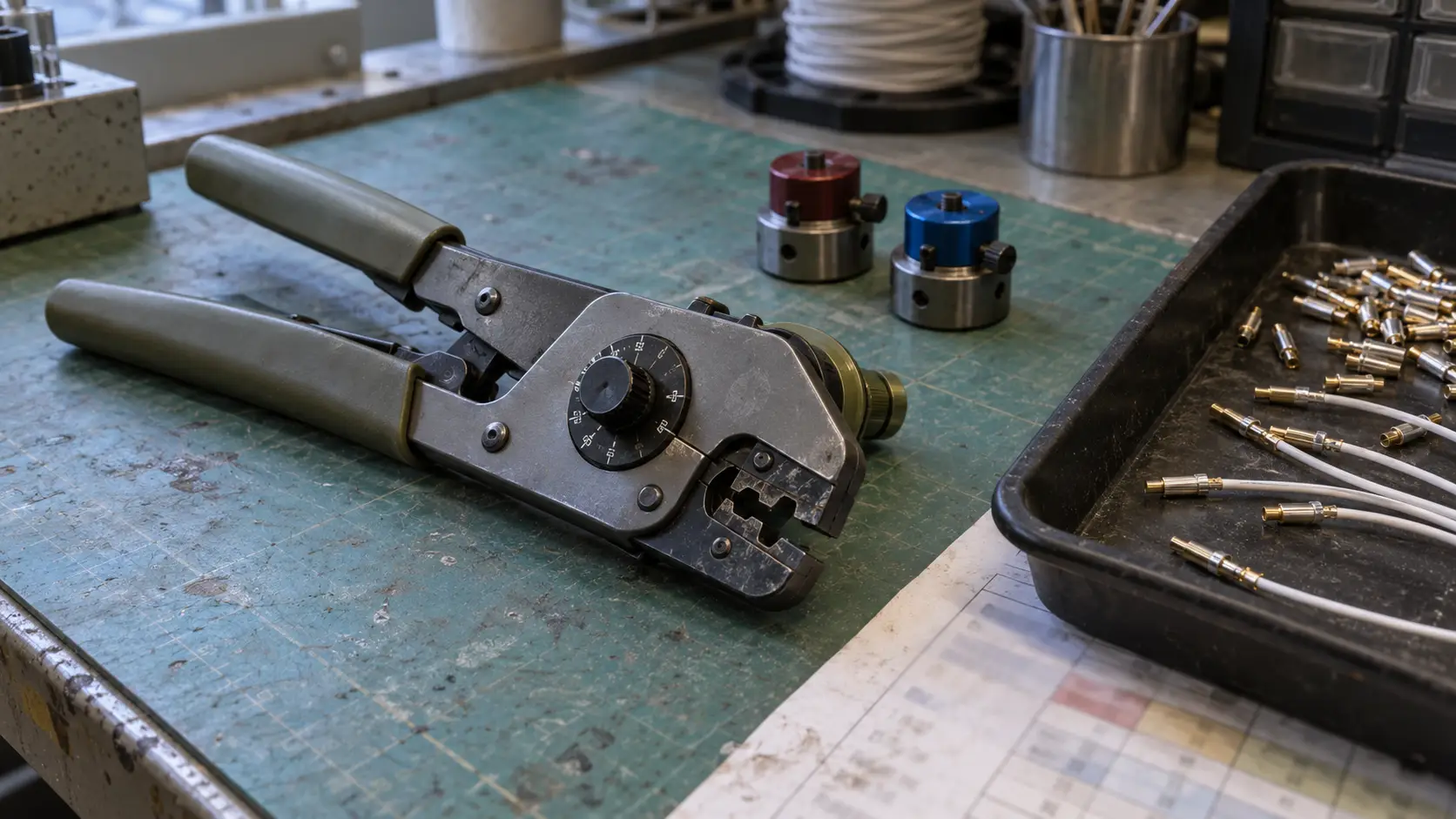
A size 22D contact crimped at the wrong selector setting will pass continuity, pass a visual check, and then go intermittent a year into service on a vibration-heavy airframe. Nothing snaps. Contact resistance climbs a few milliohms at a time until the circuit drops out at one particular frequency, and by then the harness sits behind a panel that takes half a shift to open.
MIL-spec crimp tools exist to prevent that failure. These are not general-purpose hand tools with a military part number stamped on the side, but dimensionally controlled frames qualified against a published specification and verified with a gage.
Fit the wrong positioner and none of that protects you.
What Is a MIL-Spec Crimp Tool?
MIL-spec crimp tools are hand or powered crimping frames qualified against SAE AS22520 (previously MIL-DTL-22520) to produce a controlled, repeatable indent on a machined contact barrel. The frame sets indent geometry, a positioner sets contact depth, and a selector sets indent closure. All three must match the contact you are terminating.
What happens inside the barrel is a cold weld, not a clamp. The indenters drive the barrel wall into the conductor hard enough that oxide films on the strand surfaces break up and clean metal meets clean metal under sustained residual stress. Whichever contact plating you specified governs how readily that oxide re-forms afterwards. Get that pressure right and the joint outperforms solder in vibration. Fall short by a little and you have a mechanical grip with an oxide layer still sitting in the current path, waiting for humidity and micro-motion to finish the job.
AF8 and AFM8: Two Frames With One Dangerous Overlap
Two frames cover most MIL-spec work. The AF8, qualified to M22520/1-01, handles roughly 12 to 26 AWG. Its smaller sibling, the AFM8 (M22520/2-01), covers roughly 20 to 32 AWG with an eight-impression crimp and an eight-step selector knob.
Read those ranges again. They overlap at 20 AWG.
That overlap causes a good share of the bad crimps in circulation, because it is real for wire and false for contacts. A size 20 contact belongs in the AF8 with the correct positioner. Move to a size 22D contact carrying 22 AWG wire and you need the AFM8. Wire gauge alone does not select the frame, and an operator who reaches for whichever tool is charged and nearby will eventually put a size 22D contact into a frame that closes on it at the wrong depth.
Contact size chooses the tool. Wire gauge chooses the setting.
The Positioner Decides More Than the Frame Does
Most buyers specify the frame carefully and treat the positioner as an accessory thrown in at the end of the quote. That is backwards.
The positioner holds the contact at a fixed depth and angle relative to the indenters, which decides where along the barrel the eight indents land. Fit one intended for a different contact family and the indents can creep toward the inspection window, or sit so close to the shoulder that the barrel deforms where it was never meant to carry load. What goes into that barrel matters too: conductor coating and strand construction change how the strands move under the indenters.
Turret heads complicate this further, in a useful way. The M22520/1-04 turret carries several colour-coded positions on a single head: red for size 20, blue for size 16, yellow for size 12. One head, three contact sizes, and one more chance to leave it indexed where the last job left it.
Check the index before the first crimp of every job. Every time.
Contact Size, Tool and Positioner in One Table
The mapping below covers standard-duty AS39029 contacts, the ones that populate most MIL-DTL-38999 and MIL-DTL-5015 connectors. Treat it as orientation, then confirm against the contact manufacturer's own crimp data sheet, which is the only document that governs your specific part number.
| Contact size | Wire range | Qualified hand tool | Positioner or turret |
|---|---|---|---|
| 22D | 22 to 28 AWG | M22520/2-01 (AFM8) | M22520/2-07 |
| 20 | 20 to 24 AWG | M22520/1-01 (AF8) or M22520/2-01 (AFM8) | M22520/1-04 (red) or M22520/2-10 |
| 16 | 16 to 20 AWG | M22520/1-01 (AF8) | M22520/1-04 (blue) |
| 12 | 12 to 14 AWG | M22520/1-01 (AF8) | M22520/1-04 (yellow) |
Size 20 appears twice on purpose. Both routes are legitimate, and the correct one depends on the contact's own qualification rather than on which frame is already sitting on the bench.
The Selector Setting Is Not a Suggestion
The eight-position selector changes how far the indenters close, with lower numbers closing them further.
Resist the temptation to derive that number from wire gauge. Not from a rule of thumb. The setting comes from the contact manufacturer's crimp chart for that contact and that conductor, because it accounts for strand count, plating thickness and barrel wall dimensions that a gauge number tells you nothing about. Two 22 AWG wires with different strand counts can call for different settings in the same contact.
Under-crimp and the strands are held but not cold-welded. Over-compress and you fracture strands at the barrel edge, which shows up as a tensile failure long before anything appears electrically.
A Failure You Can Reconstruct From the Wire
Picture a helicopter avionics rack going through an MRO shop. Size 22D contacts, 24 AWG wire, terminated into a MIL-DTL-38999 Series III connector on a Friday afternoon, straight after a batch of 20 AWG leads went through the same AFM8.
Nobody reset the selector.
Those 24 AWG crimps came out under-compressed, and every one passed continuity, because an under-crimped contact conducts perfectly well on a bench. Months later the aircraft starts logging intermittent faults on one bus, always in the cruise, never on the ground. Strip the connector and you find the tell: barrel indents visibly shallower than the reference sample, and strand surfaces showing oxide instead of the bright deformed metal of a proper cold weld.
Vibration did the rest. Micro-motion between strand and barrel, oxide growth at the fretting interface, resistance climbing until the margin ran out. A backshell with proper strain relief cuts the movement reaching the termination, but it cannot rescue a crimp that left the tool wrong.
The tool was qualified and the contacts were right. One knob was wrong.
Pull Testing Passes Almost Everything
Here is the position that will be least popular with quality departments: the pull test is a process-confirmation test rather than a defect detector, and treating it as the quality gate gives false confidence.
NASA Goddard analysed 780 pull force test results across NASA centres. Measured tensile strength exceeded the minimum required values by at least 100 percent, and averaged at least 182 percent of the minimum. Every sample passed.
That is a healthy process. It is also, as a screen for defects, a blunt instrument.
A pull test destroys the sample you tested and says nothing about the 200 crimps you shipped. It will not catch a wrong positioner, because a crimp landing in the wrong place along the barrel can still hold well past 57 N. NASA-STD-8739.4A sets that 57 N (13 lb) minimum for 22 AWG and 92 N (21 lb) for 20 AWG, tested at a head travel speed of 25.4 ± 6.3 mm per minute. Those are floors, and the Goddard data shows real crimps clearing them with enormous margin even where the process has drifted.
Keep pull testing. The standard asks for it at the start and end of each shift or production run, with zero failures out of three samples. Just stop reading a pass as evidence that the parts you shipped are good, because poor crimp quality belongs with corrosion and vibration among the failure modes that surface only in service.
Gaging Catches What the Pull Test Misses
Gaging verifies the tool itself, and it costs almost nothing to run.
The M22520/3-01 GO/NO-GO gage checks that the indenters still close to the dimensions the tool was qualified to. A frame that has been dropped, worn, or quietly adjusted by someone with a spanner will fail the gage while still producing crimps that sail through a pull test.
NASA-STD-8739.4A is direct about this. Calibration adjustments must be accessible only when the tool is disassembled and made only by the manufacturer or a calibration laboratory, and every adjustable crimp tool must be set, sealed or locked, and verified before use. If your tools have accessible adjustment screws and no seals, you do not have a controlled process, whatever the certificate on the wall says.
Crimp, Then Solder? Almost Never.
This comes up constantly on engineering forums, usually phrased as: for connectors designed from the outset to be crimped, what is the harm in soldering them as well?
Three mechanisms, and they compound.
Solder wicks up the strands well beyond the barrel and creates a rigid section that terminates abruptly, which is exactly where the conductor fatigues and breaks under flexing. Heat from the iron melts the insulation you just captured in the insulation grip, removing the mechanical support the crimp was providing. Thermal cycling then works against the residual stress that holds the cold weld together.
Under vibration, a correct crimp already outperforms solder by a wide margin, and adding solder does not stack the two benefits. It swaps a good joint for a worse one.
When a Hand Tool Is the Wrong Answer
Hand tools have a ceiling, and it sits lower than most people assume.
Above a few hundred crimps in a run, hand tooling limits both consistency and operator endurance, and variation starts showing up in your process data. A pneumatic or bench tool with crimp force monitoring earns its cost there, since force monitoring inspects every crimp rather than three per shift.
There is a blunter version of this. If you are terminating a few hundred Class 3 assemblies a month, buying tooling and certifying operators usually costs more than buying finished assemblies. Incotech stocks both the tooling and the contacts. At that volume the honest answer is often to buy cable assemblies built and tested to the standard instead. Tooling earns its place when volumes are low and mixed, when you need the process in-house, or when field repair is part of the job. Not as a way to save money on volume harness work.
The Standards That Changed Recently
Check which revision your purchase orders cite, because one of these moved.
IPC/WHMA-A-620 reached Revision F in October 2025. Plenty of quality manuals still call out Revision D from 2020 or Revision E from December 2022, and Revision E already brought a full rechaptering plus alignment of soldering requirements with IPC J-STD-001. A supplier certified to one revision and a drawing citing another is a finding waiting to happen at audit.
Two other documents belong on the bench. NASA-STD-8739.4A carries the tensile and workmanship numbers quoted above, and it is freely available. QPL-22520-8, the AS22520 qualified products list administered through NAVAIR, tells you whether a tool is genuinely qualified rather than merely described as meeting the spec.
A Ten-Minute Routine at the Start of Every Shift
Run this before the first production crimp, not after the first complaint:
- Confirm the contact part number against the manufacturer's crimp chart, and read the tool, positioner and selector setting off that chart rather than from memory.
- Check the turret index or positioner part number physically, with the contact in your hand.
- Gage the frame with the M22520/3-01 and record the result.
- Verify the tool seal is intact and no adjustment has been made since the last calibration.
- Crimp three samples and pull them to the value in NASA-STD-8739.4A Table 12-1, or your programme's equivalent, accepting zero failures.
- Cut one sample longitudinally and inspect the deformation, checking that insulation clearance sits between 0.25 mm and 0.75 mm for 20 AWG and smaller.
- Keep one good crimp as a visual reference at the bench for the rest of the run.
Step seven is the one people skip. An operator comparing against a physical reference spots a shallow indent long before the next gage interval comes round.
Frequently Asked Questions
What is the difference between the AF8 and the AFM8 crimp tool?
The AF8 (M22520/1-01) covers roughly 12 to 26 AWG and the larger contact sizes, typically 20, 16 and 12. Its counterpart the AFM8 (M22520/2-01) handles roughly 20 to 32 AWG and the smaller contacts, principally size 22D. They overlap at 20 AWG, so let contact size decide, not the wire.
Can I use a generic crimp tool on MIL-spec contacts?
No, not for qualified work. Machined MIL-spec contacts need a controlled indent geometry and depth that generic tools do not reproduce, and the resulting joint is traceable to no specification at all. NASA-STD-8739.4A requires four or more indenter blades, and tools that are set, sealed and verified before use.
What is the harm in soldering a crimped contact as well?
Solder wicks along the strands and creates a stiff section that fatigues under flexing, heat from the iron damages the insulation captured by the insulation grip, and thermal cycling degrades the residual stress holding the cold weld. A correct crimp already outperforms solder under vibration, so the addition makes the joint worse rather than safer.
How often should crimp tools be gaged?
Gage at the start of each shift or production run as a minimum, and again after any drop, jam or suspected adjustment. The M22520/3-01 GO/NO-GO gage takes seconds to use. Formal recalibration belongs with the manufacturer or a calibration laboratory, since adjustments should only be reachable with the tool disassembled.
What pull force should a crimped contact withstand?
NASA-STD-8739.4A Table 12-1 gives minimums by conductor size: 57 N (13 lb) for 22 AWG, 92 N (21 lb) for 20 AWG, 183 N (41 lb) for 16 AWG and 459 N (103 lb) for 12 AWG. Where a contact and conductor pair is not listed, the crimp must reach at least 60 percent of the tensile strength of the wire.
Do I need a separate positioner for every contact size?
Usually yes, although turret heads consolidate several sizes into one component. The M22520/1-04 turret covers sizes 20, 16 and 12 in colour-coded positions. Positioners are not interchangeable between contact families even at the same nominal size, so verify against the contact data sheet before ordering.
The Tool Is Part of the Specification, Not an Afterthought
Connector selection gets weeks of engineering attention. Tool selection gets a line on a purchase order, and then a technician makes the decision that determines whether the joint survives ten years of vibration.
That imbalance is the real problem, and it is fixable on paper. Put the tool, positioner and selector setting on the assembly drawing next to the contact part number. Specify the gage interval. Name the pull-test standard and the sample size.
Do that and the crimp stops being the weakest documented step in an otherwise well-specified system.
Incotech supplies MIL-spec crimping and assembly tools, contacts and interconnect accessories alongside build-to-print cable assemblies for aerospace, industrial and defence programmes. If you are matching tooling to a contact part number, or weighing up whether to bring termination in-house at all, our engineers can work through it with you.